Facade pattern: unified interface for software projects
When looking for suitable strategies to simplify complex software, one inevitably encounters the facade design pattern or simply facade pattern. Much like the decorator pattern or the composite pattern, it belongs to the category of structural patterns of the so-called GoF design patterns (the abbreviation ‘GoF’ stands for ‘Gang of Four’), which have had a decisive influence on software design since publication in 1994.
In this article, we’ll show you what the facade pattern is and how it helps developers equalise sub-systems.
What is the facade pattern
The facade design pattern is one of the 23 GoF design patterns, which were published in 1994 by authors Erich Gamma, Ralph Johnson, Richard Helm, and John Vlissides in ‘Design Patterns: Elements of Reusable Object-Oriented Software’ as guidance for software developers. In general, these patterns aim to simplify the creation of flexible, reusable software. The facade pattern defines a sample solution for the simple merging of different interfaces in complex systems. A universal facade class, which also functions as an interface, delegates important functionalities of the software to the respective sub-systems in order to make handling the various sub-components of a program as simple as possible.
What problems does the facade pattern address?
Clients that access a complex sub-system refer directly to a large number of objects with completely different interfaces or are dependent on these objects. This makes the implementation, adaptation, testing, and reuse of the clients particularly difficult for developers. This is where the facade design pattern can be useful.
The facade design pattern defines a central facade object that:
- implements a universal interface for the various interfaces of the sub-system(s).
- and (if necessary) can perform additional functions before or after forwarding a client request.
As an intermediary, the facade object ensures that access and communication with the individual components of a subsystem are simplified and direct dependence on these components is minimised. It delegates the client calls so clients don’t need to know the classes or their relationships and dependencies.
 To display this video, third-party cookies are required. You can access and change your cookie settings here.
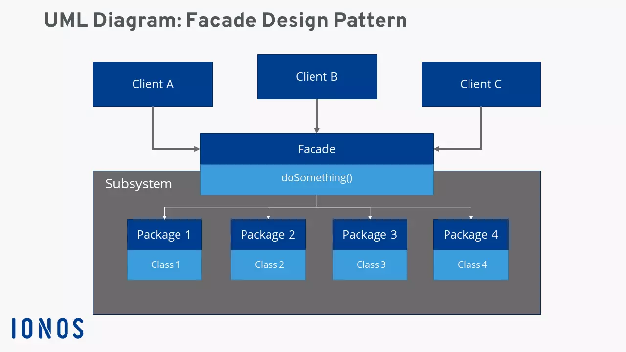
 Facade pattern: UML class diagram of the design pattern
The facade or the facade class is the decisive structuring unit of the facade pattern. In other words, its implementation and preparation is the fundamental task for developers looking to simplify their complex software by using this handy design pattern. Once implemented, the client objects communicate with the facade class, which in this new system is the only instance on which the clients are directly dependent.
The following UML diagram illustrates the interaction of clients, facade, and sub-system classes according to the facade pattern.
Facade pattern: advantages and disadvantages
The advantages of the facade design pattern are obvious: The facade ‘hides’ the underlying software sub-systems and thereby reduces the complexity of these systems. In addition, the approach promotes the principle of loose coupling. Due to the low degree of interdependence of the individual components, changes (modifications, maintenance) are convenient and possible at any time. Because of loose coupling a sub-system is easier to expand.
If clients are dependent on direct access to certain classes of the sub-system, this can also be granted in the facade pattern model. In this case, only the visibility of the sub-system needs to be programmed so that a client can bypass the facade if necessary.
However, the use of the facade design pattern has some disadvantages. Because of its central role, the implementation of a facade is a tedious and complicated task, especially if it has to be inserted into existing code. In general, the installation of a facade interface requires an additional indirection stage, that in turn increases computing time for method and function calls, memory access, etc. Finally, the facade pattern also harbours the risk that the software becomes too dependent on the central master interface.
| Advantages | Disadvantages |
|---|---|
| Minimises complexity of sub-systems | Complex implementation (especially with existing code) |
| Aids principle of loose coupling | Approach is coupled to an additional level of indirection |
| Software becomes more flexible and easily expandable | High degree of dependence at facade interface |
Typical use cases of the facade design pattern
The properties of the facade design make it an interesting pattern for several application scenarios. Above all, there is the desire for a uniform interface to access complex sub-systems or any number of objects. A facade promises to simplify things here. That’s why the use of the facade pattern strategy should play a major role when planning a project.
Another typical application is software in which the dependency between clients and underlying subsystems is to be minimised.
Finally, the facade pattern is a useful approach to plan software projects that have multiple layers. The facades act as communication interfaces between the individual layers, increasing flexibility and the possibility of extension and adaptation of components.
Practical example of facade pattern implementation
The facade design pattern is connected to specific programming languages. The pattern is typically used with C++, C#, JavaScript, Java, PHP, and Python. The following facade pattern example is based on Java and taken from tutorialspoint.com.
In this example, a universally applicable interface ‘Shape’ is to be defined for objects that represent a geometric form. In addition, concrete classes are generated which implement the interface as well as facade classes called ‘ShapeMaker,’ which are responsible for delegating client queries.
First, we create the interface Shape.java using the following code:
public interface Shape {
	void draw();
}
Secondly, three concrete classes are created that implement the interface: Rectangle.java (class for rectangle objects), Square.java (class for square objects), and Circle.java (class for round objects).
public class Rectangle implements Shape {
	@Override
	public void draw() {
		System.out.println("Rectangle::draw()");
	}
}
public class Square implements Shape {
@Override
public void draw() {
System.out.println("Rectangle::draw()");
}
}public class Circle implements Shape {
@Override
public void draw() {
System.out.println("Rectangle::draw()");
}
}Finally, the facade class ShapeMaker is integrated into the code which will be called upon by the clients to create the different shapes:
public class ShapeMaker {
	private Shape circle;
	private Shape rectangle;
	private Shape square;
	public ShapeMaker() {
		circle = new Circle();
		rectangle = new Rectangle();
		square = new Square();
	}
	public void drawCircle(){
		circle.draw();
	}
	public void drawRectangle(){
		rectangle.draw();
	}
	public void drawSquare(){
		square.draw();
	}
}

