UML component diagrams: efficient modelling systems with software modules
The Unified Modeling Language (UML) is a commonly accepted ISO standard for developing software and more complex system architectures. This modelling language uses different types of diagrams for planning and development processes in object-oriented programming.
The latest version (UML 2.5) has 14 different diagram types which are roughly divided into two categories: behavioural and structural diagrams. The latter category includes component diagrams. In the following, we will explain what a component diagram is and explain how to draw a component diagram through a concrete example. You will also learn what UML component diagrams are used for.
- Free website protection with SSL Wildcard included
- Free private registration for greater privacy
- Free 2 GB email account
What is a component diagram?
UML component diagrams show the relationships between individual system components through a static conceptual visualisation. Both logical and physical modelling aspects can be included.
In UML, components are modular parts of a system that are independent and can be replaced with equivalent components. They are self-contained and encapsulate structures of any complexity. The encapsulated elements interact with other components exclusively via interfaces. In addition to having their own interfaces, components can also use the interfaces of other components, such as to access their functions and services. The interfaces also document the relationships and dependencies that exist in a software architecture in a component diagram.
Encapsulation prevents direct access to the internal data structure, which could prevent unauthorised access to the data. Defined interfaces control access and provide a user with access to only the relevant methods and data elements.
Components usually encapsulate classes and are thus also described as a sub-form or specialisation of a class. Similar to a class, they have a composite structure and can be more precisely defined using attributes, methods, operations, and so on. Components can be a collection of classes and can, for example, be implemented at runtime by one or more classes. Although components are often equated with classes, there are some differences. While components generally require interfaces for interaction, classes can also access a method directly.
In object-oriented programming, a class functions as an abstract model that describes a set of similar objects. They have the same attributes, operations, relationships, and so on.
The notion of components has a broad definition in UML. Components include various parts of the system, such as databases, packages, files, and libraries (e.g. dynamic-link libraries or DLLs). In addition to technical components (e.g. for database access), there are also specialised components that can relate to areas such as business and business processes. These relationships can be more complex, so UML provides the stereotype <<subsystem>> to describe them.
Since component diagrams are modelled with an implementation-oriented design, there are special implementation components that focus on individual implementation aspects. These components can be used, for example, to implement other components such as executables (i.e. executable files with the extension *.exe) in Windows.
Implementation refers to the concrete execution of a developed software or previously planned system. This can be the concrete execution of a developed program or of individual functions and algorithms.
Multiple components come together to form a more complex system architecture. Components can also contain other components and build on each other, so a component can require another component (i.e. a dependency relationship). In addition, software modules can refer to different phases of execution. Some components are primarily used for planning and development in the design stage, while other components are used at the software’s runtime. These are also referred to as design and runtime components.
Runtime refers to the time span in which a program is executed and performs a task.
What are UML component diagrams used for?
A component diagram provides an overview of a system from a bird’s eye perspective which documents the organisation of system components and their interrelationships and dependencies. Component diagrams provide an implementation-oriented view, thus giving the developer insight into whether a system functions as a whole and fulfils its tasks and objectives.
The main objectives and uses of this diagram type are to model component-based software systems, define software architecture and divide systems into subsystems (e.g. graphical user interfaces (GUI), business fields, and persistence in relational databases). In addition, these subsystems and their interfaces are assigned specific tasks and functions inside a system.
In the business world, UML component diagrams are an important means of exchanging information with the customer since they help reduce the complexity, thus making projects and plans easier to understand and to communicate to others. Component diagrams also support and simplify software development administration, such as by combining classes into manageable components.
The modular approach of this diagram type also helps to make projects more cost-effective and efficient since software systems can be modelled as structured functional relationships from reusable components. For example, component diagrams clearly visualize which building blocks can be used multiple times and where in the architecture. System designs can be optimally oriented towards reusing components and ensuring they interact efficiently.
Component-based software systems help save time and money in the planning and implementation phase of a system since existing elements can be reused. In addition, using tried and tested software modules reduces potential risks and sources of error, especially when implementing more complex projects. You can also compensate for a lack of in-house experience and knowledge since third-party modules can be purchased to implement systems.
What are the elements of a component diagram?
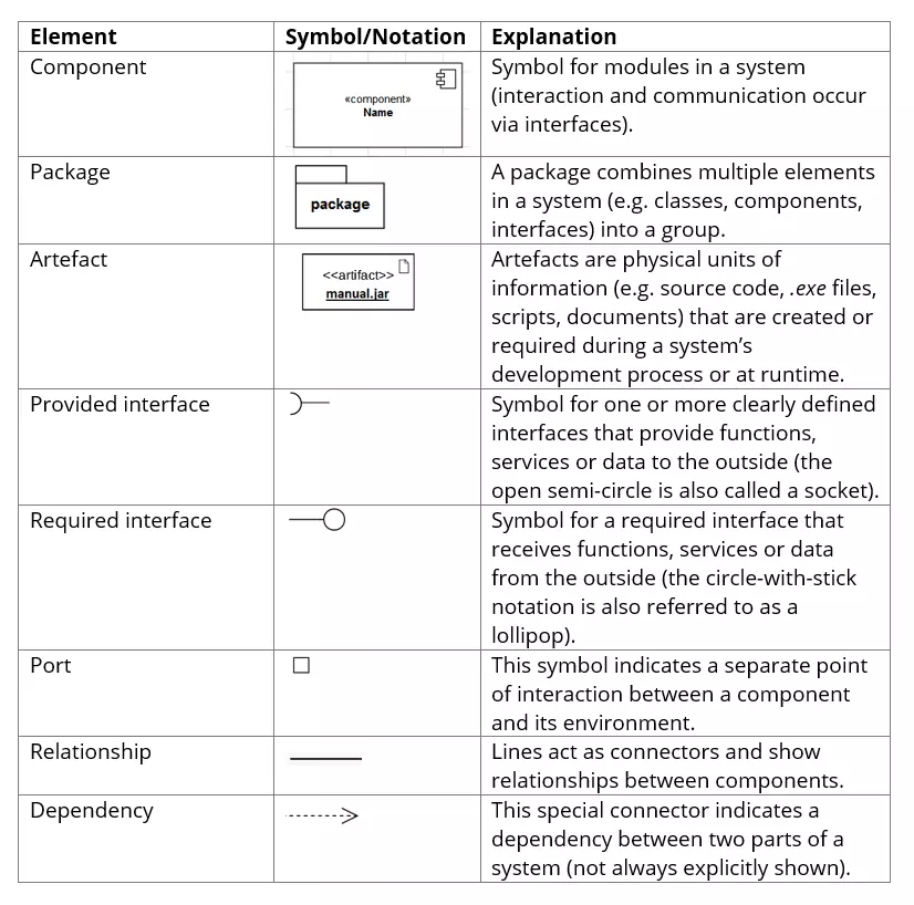
You could use these basic elements to draw a simple component diagram using the free open-source software JGraph.
How to draw a component diagram explained using an example
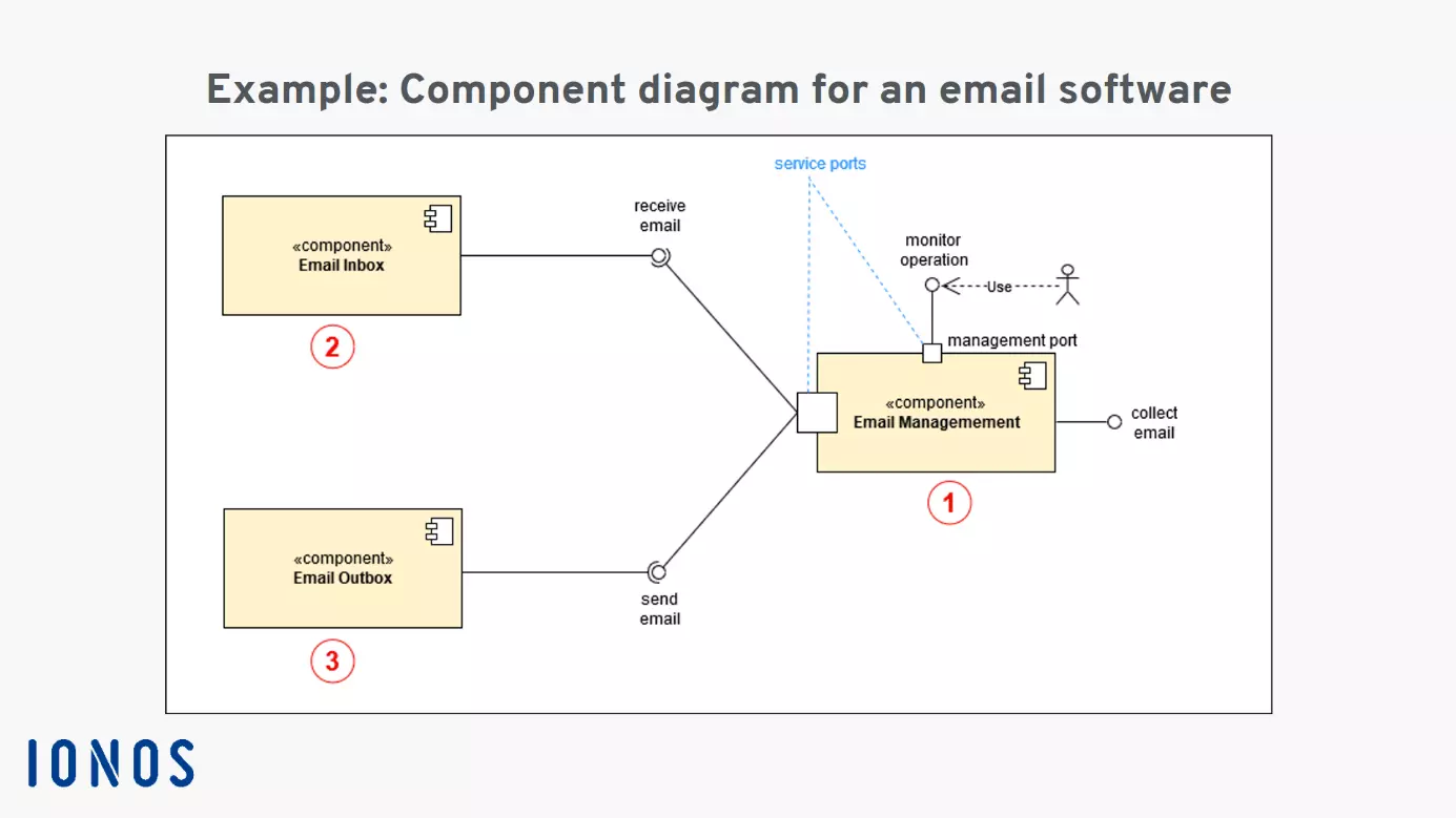
In our component diagram example, we will show you how the structure and functions of an email program are visualised. This component model illustrates how three basic modules interact via interfaces:
- email management (1)
- incoming email (2)
- outgoing email (3)
Email management (1) is the control centre of this system, interacting with users and other software modules via multiple interfaces and service ports. To enable users to monitor whether everything is running smoothly, an interface and a service port (management port) are provided for system administration. The “use arrow” with the dashed line indicates that the user is dependent on this interface to perform their administration tasks.
Systems and components outside the modelled architecture can be connected to the system via the provided interface labelled “Retrieve email”. Functions and data required by the outgoing email module (3) are provided by the management module via the implemented and provided interface labelled “Send email”. The management module also uses services and functions via the “Receive email” interface for the incoming email module (2). Graphically, the connections between components are represented with ball-and-socket joints for the interfaces.
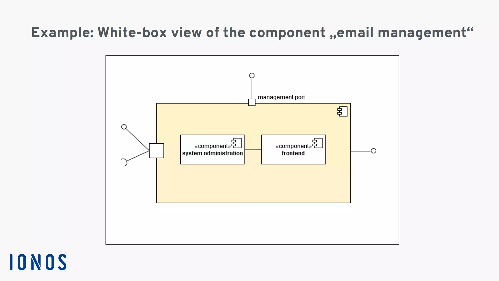
The example diagram shows the system components in a black-box view which disregards the inner workings to provide a clearer overview. In a white-box view, a component diagram will show the inner structure of components. For example, the management component (1) could contain the functional sub-components “frontend” and “system administration” which help the administrator with system management.

The level of detail in a component diagram can be further enhanced by defining the elements involved even more precisely using the UML standard. For example, a class can be defined more precisely using attributes and operations. The options for more precisely defining classes are described in detail in our article on class diagrams. Additional drafting and modelling options include use case diagrams and state diagrams.


