Activity diagrams: clearly present chronological activity processes with UML
The activity diagram is a diagram type within the “Unified Modeling Language” (UML). This graphical modeling language defines forms for representing object-oriented programming. It specifies 14 diagram types. Certain forms are assigned to these. With the help of notation rules, systems and processes can be abstracted and clearly presented. UML models not only software systems, but also business processes. Activity diagrams are particularly useful in both areas. But why should you create an activity diagram?
The purpose of activity diagrams
UML activity diagrams belong to the group of behaviour diagrams in unified modeling language. While a structure diagram records the state of a system, i.e. the existing objects and their hierarchies as well as connections to each other at a certain point, behaviour diagrams describe the chronological flow of data streams. In addition to the activity diagram, the “use case diagram” and the “state machine diagram” belong to this group. Activity diagrams are similar in use and notation to flowcharts (especially program flowcharts), but are tailored to object-oriented programming.
Basically, it can be said that the activity diagram models the flow of activities. These can be processes within a computer system, use case processes, or business processes. For example, the activity "preparing a cheese omelette" can be broken down into many small sub-activities: the actions. These can take place chronologically. One action would be "breaking eggs," followed by the action "whisking eggs while seasoning." The first action requires the second. They're in flux, so to speak.
Parallel processes can also be illustrated. If two people are in charge of preparing the omelette, this enables the actions to be carried out simultaneously i.e. breaking eggs and chopping herbs. This means that the activity has two starting points. The people start their activity at these points and go from one action to the next. Although these two people play an important role in the activity diagram, they don’t have their own notation. You move from a starting point to an end point, crossing control or object flows to move from one action to the next. In between, there are occasional barriers, so-called pins, which they only let things through under certain conditions e.g. when both persons are present.
In the activity diagram, these “persons” are referred to as tokens. There are two types of tokens in the UML activity diagram: the first is the object token, which transmits information to the action node, starts an action there and (if specified) saves the result as a value. If the result and token correspond to the specifications defined in the pin, this output pin sends the object token via an object flow to the next action. Before the token can start this action, it must comply with the input pin specifications. Control tokens, on the other hand, only migrate over control flows and serve as markers. You start an action but do not transfer any data.
In the example described above (“preparing a cheese omelette”), we use the activity diagram to illustrate the time sequence of a use case. Use case diagrams, on the other hand, illustrate the system requirements that should be met for a use case.
UML 2 activity diagram don’t solely have to be used for everyday scenarios. First and foremost, they help you to illustrate the processes in software systems in a structured manner. This way, business analysts, for example, set guidelines for software developers. The experts exchange information about the graphic language on a generally understandable and clear level. Once all processes have been settled and errors ironed out, the activity diagram serves as a clean template for programming.
If you integrate a suitable UML tool into your integrated development environment, the diagram can act as a code framework into a programming language using XML conversion.
The Object Management Group (OMG), which specifies the UML, summarises the possible tasks of UML 2 activity diagrams.
- Procedural computer programming that assigns hierarchies to activities
- In objectoriented models, activities act as methods that describe processes in more detail
- For illustration workflows and business processes
- In computerbased application systems, activities specify processes at system level
The notations for UML activity diagrams
The forms within the UML can be understood as the building blocks of the language. So, the modeling language assigns meaning to each form. Modifying factors describe them in more detail and relate them to each other. In addition, shapes sometimes require certain other shapes or labels to create a meaningful diagram. Just as spoken language only makes sense if certain basic grammatical rules are observed, UML only functions as a means of communication if you comply with the specifications.
UML 2.5 is the most current specification of the modeling language, and so forms the basis of this presentation. UML defines the notation of the diagram types based on their application areas. Since the UML activity diagram illustrates the flow of system processes and use cases, metamodeling assigns appropriate forms to it.
How are the individual components visually represented and which functions do the symbols in the UML activity diagram have?
Activities
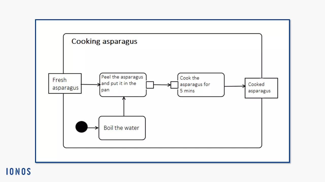
UML 2 specifies an activity as behaviour that underlies subordinate units (actions and objects) in an order. It uses data and control flow models to do this. The activity diagram can be displayed as part of a larger system in conjunction with other diagram types. A large, rounded rectangle indicates the activity as a closed system (can also be omitted). Below in the example image, you can see the activity “cooking asparagus.” The title is written in the header of the large rectangle. The body accommodates edges (arrows) and nodes (rectangles). These symbolise the detailed actions, objects, and control or data flows of the activity.
Activities are considered classes in UML (their metaclass is the behaviour). Therefore, they can be determined more precisely by properties. This can influence subordinate elements. An activity is considered completed when a token has moved from its starting point through the actions to the end point. The end point destroys the token. This also applies to all other tokens, so that the activity stops all synchronous actions.
UML 1 defines activity diagrams differently from UML 2; the earlier version assigned them the role of a specialized state machine diagram, limiting their areas of application. So, if you are using a UML tool, you should make sure that it supports the desired formulation – ideally UML 2.5 or higher.
Actions: activity nodes that illustrate the behaviour
An action (executable node) is a model element that is hierarchically subordinate to the activity: the action is an instance of the class, “activity.” Actions represent behaviour within a system. They are the basic building blocks for expressing behavior in UML. They are used both in activity diagrams and in interactions.
When you create an activity diagram, use the notation “action” to display the executable subareas of an activity. In the example above, “peel the asparagus and put it in the pan” is a step further towards the completion of “cooking asparagus.” Actions collect input information, process it, and produce output information. An action does not stop until it has been completed.
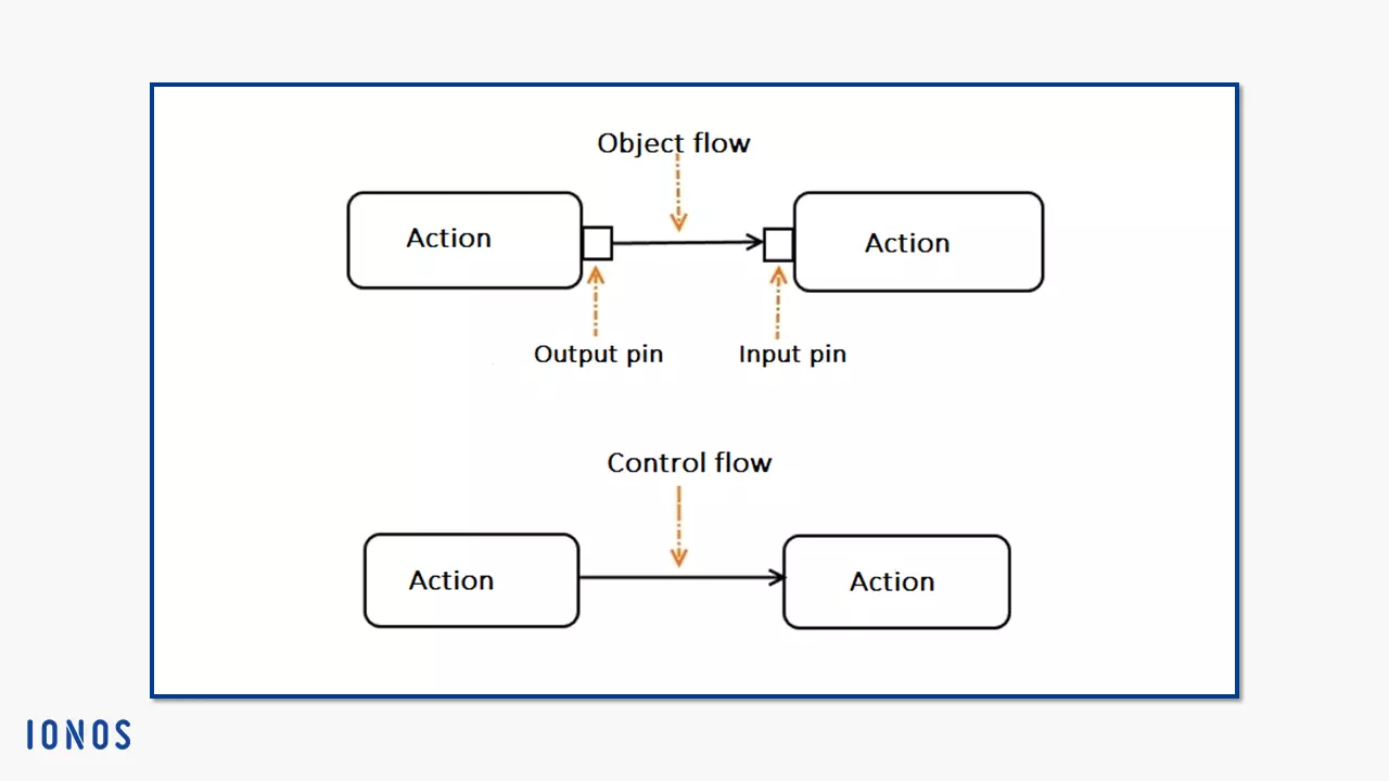
Within the UML activity diagrams, actions belong to the activity nodes. So-called edges (arrows) connect the actions with one another. UML distinguishes between object flows (data flows) and control flows (transports control token). Actions only process control flows. When data flows move between actions, pins (object nodes) accept the object tokens as input, convert them for processing the action, and then generate the object output, which moves on as object tokens.
The activity nodes category was introduced in UML 2. There are three subtypes: control nodes, object nodes, and executable nodes (the actions). There are no hierarchies between these three. As long as they are not connected in series or defined in more detail within an activity group, they can be executed in any order (as soon as incoming tokens fulfil the conditions set for a node) or in parallel.
Only if the conditions set on the pins are met, will an action (input pin) be entered or will result (output pin). Even if an action has several incoming control flows, each individual must offer a token before an action starts.
For actions within an activity diagram, the abstract syntax contains the simple form of the rounded rectangle. However, there are specific actions that modelers can use for more precise descriptions. Some of them are expressed in UML with their own notations. These are the subtypes of actions:
- Opaque actions act as placeholders or are specified by concrete text syntax (not defined by UML).
- Invocation actions are actions that cause a certain behaviour – directly or indirectly. These include:
- Call actions: a call behavior action directly instigates a behaviour. A call operation action, on the other hand, sends a request to an object that instigates a related behavior. The start object behaviour action directly causes an object to execute its instance behaviour. If none is defined, it can trigger the higherlevel class behaviour (classifier behavior).
The notation of an action that causes behaviour consists of a rounded rectangle. This is where you enter the name of the behaviour you want to instigate. Call behaviour actions are also marked with a trident icon, as shown in the picture below. This is to represent the further hierarchical branching that results from the action.
- Send actions: Send actions in the activity diagram always send data asynchronously (sequence diagrams also know synchronous messages, for example). This means that they do not wait for a response from the target object and don’t block the object flow. The action ends as soon as the message has been sent. So, it can have an “argument” input e.g. parameter, but does not produce a “result” output. In addition, messages can be sent to several recipients at the same time. Send signal action, broadcast signal action, and send object action belong to this type.
Send signal actions differ in their notation from the usual form (the rounded rectangle). Instead, a pentagon points like a large arrow in the direction of the transmitted signal. If the content of a send object action also consists of a signal, you can use the same notation.
- Object actions change the state of objects (instances of a class). You can create or destroy them, compare them with other instances, read them, and then assign them to a class or change the classification. The following instances of object actions then exist in UML 2:
- “Create object actions” generate instances of a class i.e. objects
- “Destroy object actions” destroy the object on your input pin
- “Test identity actions” examine whether two values on your input pin represent the same object.
- “Read self actions” determine their own context object.
- “Value specification actions” examine value specifications (the notation carries the label “value specification”)
- “Read extent actions” find all objects of a class and objects from its specifications (for practical reasons, modelers usually limit the range)
- “Reclassify object actions” change the class for the object on your input pin
- “Read is classified object actions” determine whether an object on your input pin belongs to a class
- “Start classifier behavior actions” trigger a behaviour for an object that is determined by its class (the behaviour is then asynchronous)
- Link actions change the behaviour of associations (relationships between classifiers, usually two classes) and their instances, like links. These include:
- “Read link actions” retrieve values (link end data) on an association’s page
- “Create link actions” are actions that create links (they do not have output pins because links are not data themselves) and link objects
- “Destroy link actions” delete links and link objects if they correspond to a specified link end data value
- Link object actions influence the behaviour of link objects, but view the objects from different perspectives. These are instances of link object actions:
- “Read link object end actions” call up end objects from link objects
- “Read link object end qualifier actions” call up classifiers end values from link objects
- “Create link object actions” are special link actions that are used to create link objects
- Structural feature actions determine the behaviour of structural characteristics in activity diagrams. To do this, they require an input pin, since they are usually assigned both an object and a statically specified structural characteristic of a classifier. The structure characteristic action affects both elements. The following types are available:
- “Read structural feature action” reads the values of the structure characteristics and forwards them as output
- “Add structural feature value actions” require a value input pin which specifies the value that the action assigns to a structural feature
- “Remove structural feature value actions” subtract a value from a structural feature (a value input pin with multiplicity of 1. 1 specifies this value)
- Variable actions influence statically specified variables defined by an activity or structured activity node. There are three types:
- “Add variable value actions” also require a value input pin, but must be of the same type as the variable and adds exactly one value to it
- “Remove variable value actions” remove a value specified by the pin
- “Clear variable actions” remove all values of a variable
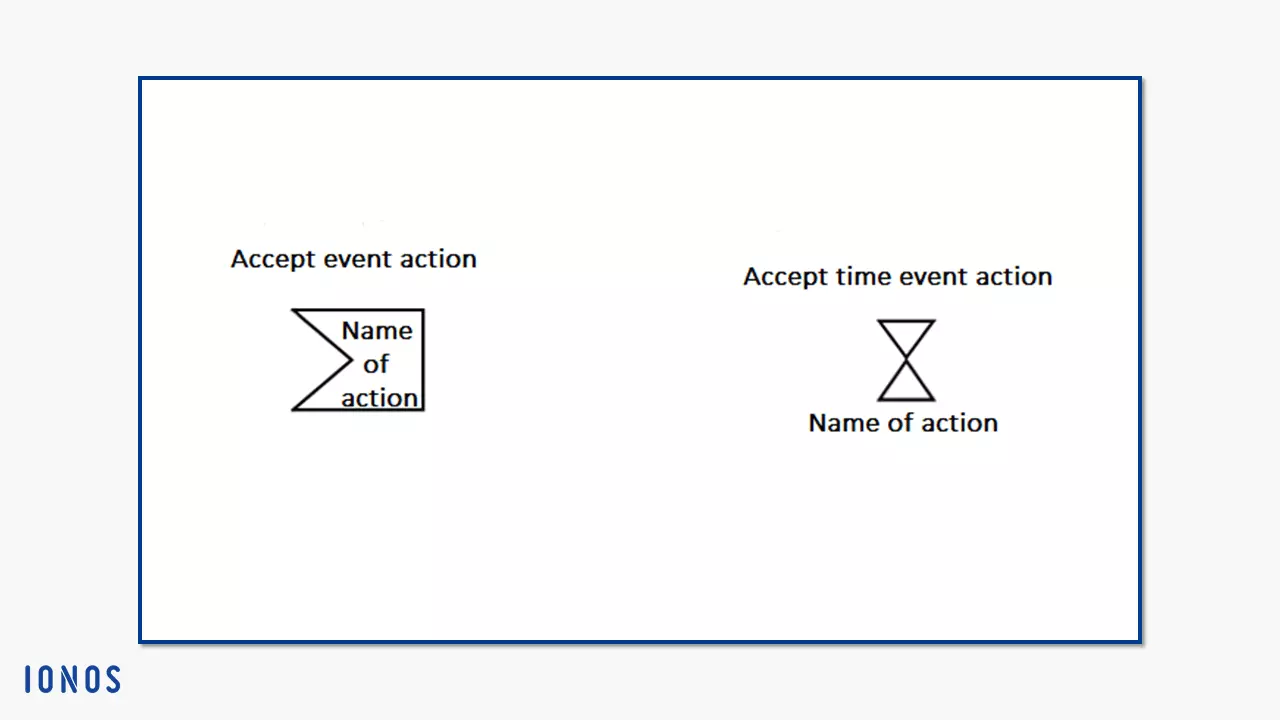
- Accept event actions belong to the so-called wait points. This means that the action is waiting for an event from the event pool of the context object. The action has triggers that set off the action when one or more prescribed states occur. UML describes three specialisations:
- “Accept call actions” have a trigger that accepts call events: two result output pins and a return information output pin complete the arrangement (if a reply action is to be executed, store the necessary information in the return information output pin)
- “Reply actions” have a connection to the accept call actions: On the one hand, the triggers should match so that the response action can react to the previously executed call acceptance action in the case of a call event, on the other hand, the higherlevel behaviour places its output value in the return information input pin of the reply action
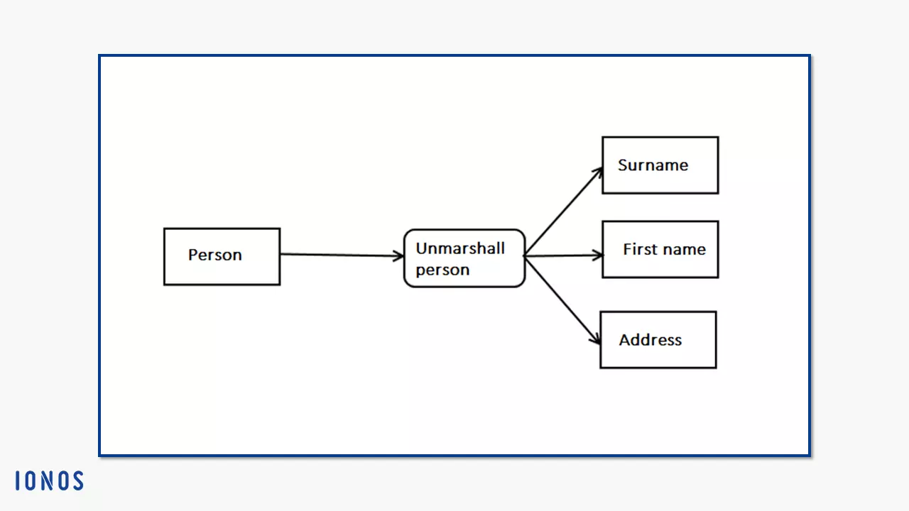
- “Unmarshall actions” query the values of object structural features (to recognise the object, they have an object input pin; the values obtained are issued on an output pin)
If structured data of an object or elementary data of a program has to be transferred to other programs or program sections, or if you want to save it, you have to convert it into a suitable format. This process is called marshalling. The opposite process, unmarshalling, converts this “frozen” data back into executable objects. An example of this is the transfer of UML diagrams from one tool to another program using XML conversion.
- Structured actions declare UML 2 in the activity diagram both as actions and as an activity group (see above). This means, on the one hand, that their behaviour is determined by activity nodes and edges, and on the other hand, that certain subtypes of these actions stipulate a certain behaviour for the executable nodes due to their semantics – especially with regard to their sequence.
These are the subtypes of structured actions:
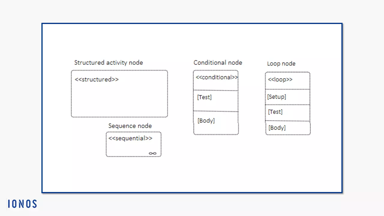
- Conditional nodes consist of one or more clauses that represent the different branches of the possible executable actions. A clause contains a test segment and a body segment, which in turn contain cutquantity-free executable nodes. First, the clause executes the action in the test area. If its output value is “true,” the clause executes the action in the body area.
- Loop nodes describe a group of actions that are repeated within a loop. The actions are divided into three sections: “setup,” “test,” and “body.” The loop always executes the “setup” first. This is followed by “test” or “body,” which is then repeated alternately.
- Sequence nodes impose an order on the executable node within their limits. You display these with data flows as activity edges (i.e. simple arrows). Edges can point freely into and out of the structure.
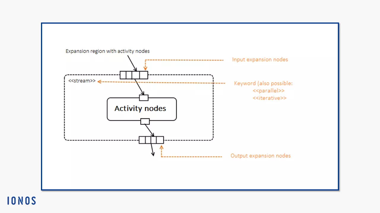
- Expansion regions are another form of structured activity nodes. You accept one or more collections of values as input. On its way to the expansion region, the input pin copies each incoming token to the number of collection elements. All inlying nodes process themselves at each individual value of the collection. A run is considered an “expansion execution.” An expansion node (a type of object node) indicates the interface of the expansion region. On the outside, they display their values as a collection, on the inside, the individual elements of the collection are considered as values. Draw a rounded rectangle with a dotted line for the notation. The expansion nodes appear as rectangles with segments and, as shown below, are drawn directly on the line. The segmentation should represent the list of value collections.
- Reduce actions call up a behaviour until a single value emerges from a collection of values. To do this, the action combines the collection elements. The action therefore has two “in” parameters, but only one “out” or “return” parameter.
- Raise exception actions (actions that cause an exception) terminate themselves as soon as they cause an exception. Therefore, they do not terminate like normal actions that stop when the action is finished. They spread outwards through the system to the next higher structured activity node. If it has a handler that corresponds with the exception, it stops the action. Otherwise, it will spread further.
Object nodes: activity nodes that control object tokens
Object nodes are subtypes of activity nodes. In general, an object in UML is the smallest instance with values. In the activity diagram, objects represent data. While an action is being executed, the object nodes hold this data. Because only control tokens can go directly through an action. Object tokens, on the other hand, are received as a value for an input pin and are forwarded by the output pin on the object flow.
Object nodes were first introduced in the UML 2 activity diagram. They are typed elements. If an object node corresponds to a certain type, the object tokens that move on it must have corresponding values. An exception are null tokens that manage without a value – they conform to each object node.
Object nodes dictate the sequence in which tokens leave them. There are four ways to do this:
- Unordered (not specified)
- Ordered (behaviour defined by the modeler)
- FIFO (first in first out): the order of entry and exit remains the same
- LIFO (last in first out): the order is exactly the opposite
If you want to create an activity diagram, you have four types of object nodes to choose from for modeling:
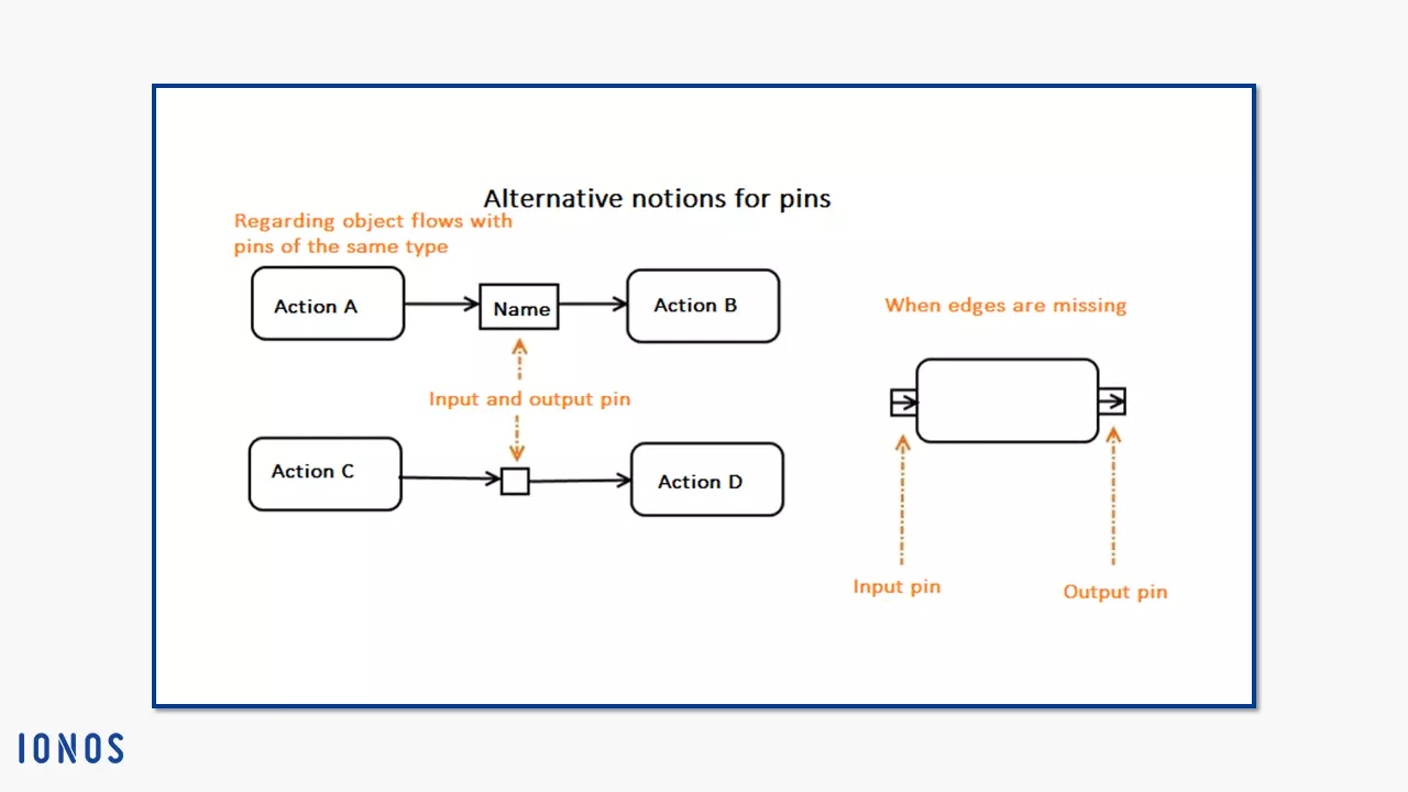
- The pin: Pins have already been cut in this version. In the first graphic, the basic notation of pins is shown. Due to their function as a link between action flows and object flows, modelers usually draw them as small rectangles directly on the action symbol. Input pins are marked with an arrow (i.e. an edge or an object flow) in the direction of the action. For output pins, the arrow leads away from the action. The following graphic shows how you can shorten pins of the same type (left) or how you can draw input and output pins if you omit the edges (right).
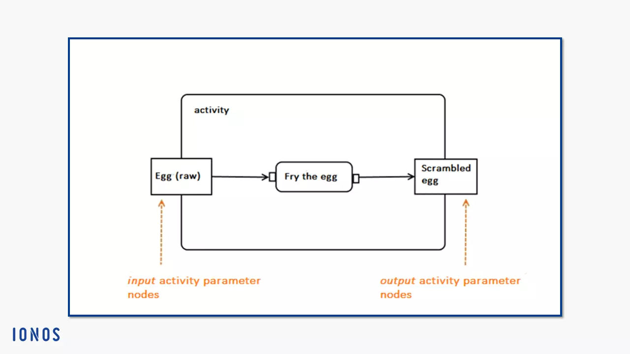
- Activity parameter node: The activity belongs to the metaclass of the behavioral description. According to UML, each behaviour has parameters. Before a behavior is executed, you can feed values into it for processing. New values are returned after processing. The parameters in this structure are the placeholders that allow these values to be entered or issued. The activity parameter node performs this task for the UML activity diagram. This means that activity parameter nodes are at the beginning and end of an activity.
As a result, nodes like these either have only incoming or only outgoing activity edges. Input activity parameter nodes are drawn with outgoing edges, and output activity parameter nodes with incoming edges. There is one activity parameter node for each parameter, both of which have the same type.
- Buffer nodes: Similar to pins, the buffer node (central buffer node) is used directly in the activity diagram. This object node stores or buffers values anywhere in the diagram. In contrast to the pin, however, it stands on its own without being bound to an activity node. The buffer node uses the object flow to connect incoming and outgoing objects with other object nodes e.g. with a pin.
As with all object nodes, the data storage node is displayed as a rectangle. To differentiate, write the stereotype “<<datastore>>” in the header.
The buffer node is used to buffer incoming and outgoing object flows. It accepts all incoming object tokens and makes them available for outgoing object flows. Only when an object node becomes free at the other end of the flow and accepts the object parameters, will the token get forwarded. According to UML notation, this mode consists of a simple rectangle. You can display its special functions with the stereotype “<<centralBuffer>>.”
- Data storage node: Like buffer nodes, you switch data storage nodes between object flows without binding them to an action. This subtype of buffer nodes has a special feature: It stores a copy of each token sent until the higher-level activity is completed. However, each value exists only once on the data storage node. If the node already stores an object token with a fixed identity, it does not accept any new tokens with exactly the same properties.
Control nodes
Within a UML activity diagram, tokens move through various actions until the activity is completed by the first token arriving at the end node. Since several tokens can pass through this process at the same time, a certain order is required. Use control nodes to ensure a clear process flow. These only manage control flows along your path from the beginning of the activity diagram through the actions to the end of the activity. Control nodes cannot cache tokens, unlike object nodes such as the buffer node.
A significant difference between object and control flows is that only control tokens migrate on control flows. Unlike object tokens, these tokens do not carry any data. They are merely markers. So, actions do not require object nodes (especially pins) to accept and pass on control tokens. A control token starts an action, moves to the next one and then sets it in motion. It controls the chronological execution of the activity.
Among the UML activity diagram symbols, the control nodes are probably the most diverse. They belong to the activity nodes. Here are six types of UML 2:
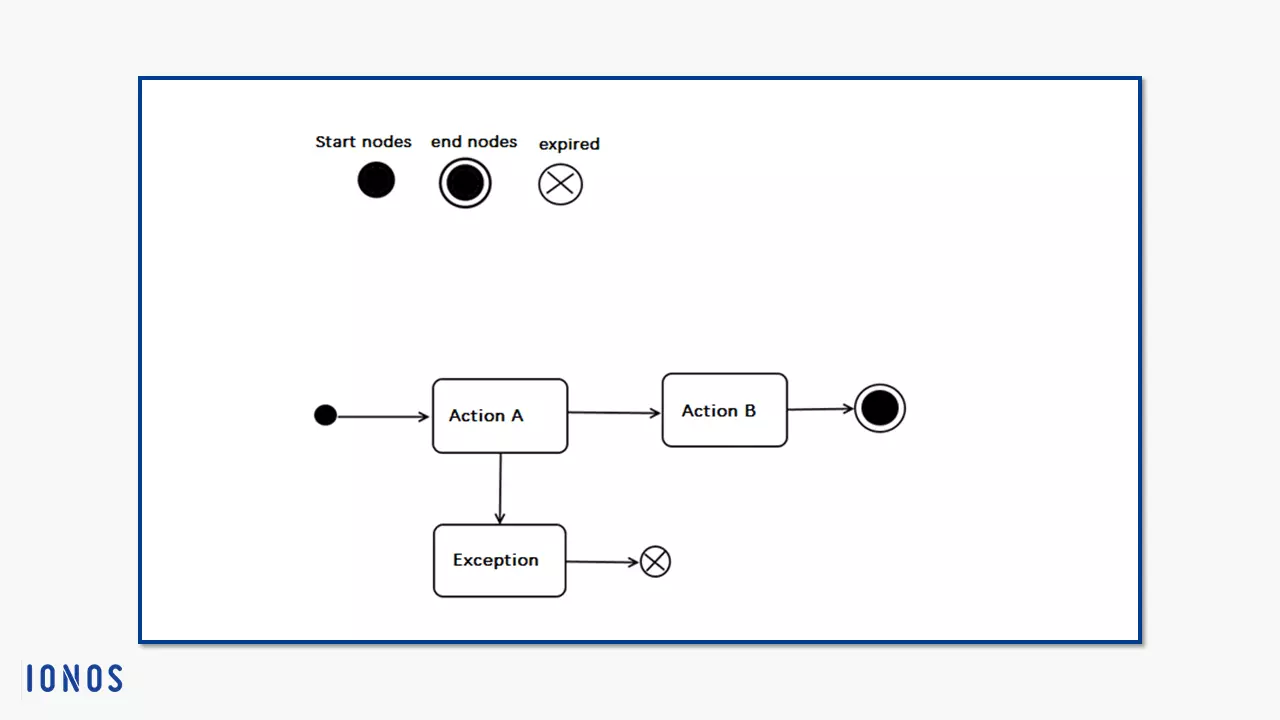
- Start nodes (initial nodes) start an activity. When an activity starts, the start node immediately sets the control flow in motion. If several start nodes exist, the respective control flows start simultaneously. Structured activity nodes can also have start nodes. These also start immediately when the structured activity is initialised, as long as no conditions for the start have been set. Since initial nodes are at the beginning, all their edges are outgoing activity edges. These are always control flaws.
Another special feature of starting nodes: The control tokens placed on the start node at the beginning of an activity can stay there if the control flow does not accept the offered token or is blocked.
- End nodes end the flow of an activity. There are two types of end nodes: The activity final node ends the entire activity by destroying all tokens within the activity when the first token arrives. Only object tokens in the output of activity parameter nodes are retained. It also stops all synchronous actions. Asynchronous actions run until they are completed. End nodes accept all incoming tokens. Unlike the start node, an end node only has incoming activity edges. More than one end node is possible.
If you draw an activity diagram with more than one end node, actions might possibly stop before they have served their purpose, because a token has already reached the first end point. The flow final node stops a control flow and destroys all incoming tokens. This does not affect other control flows. This end node is a practical alternative if you model several end points in the activity diagram.
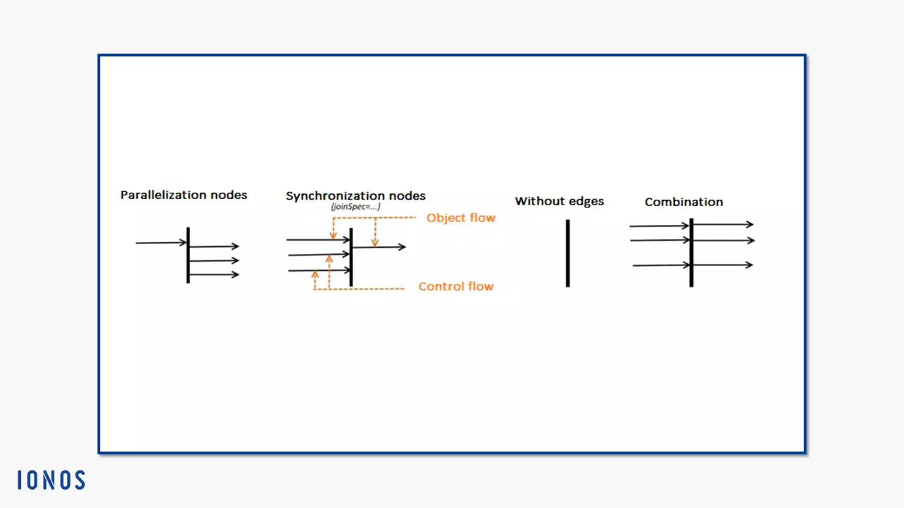
- Parallelisation nodes and synchronization nodes (fork nodes and join nodes), also called forms, are control nodes with almost identical notations that mirror their tasks. A parallelisation node divides an incoming activity edge into several, simultaneously outgoing flows. Only one activity edge can enter the parallelisation nodes. If it is a control flow, all outgoing edges are also control flows; the same principle applies to object flows. The node creates copies of the incoming token for all outgoing flows. If a token is accepted at the destination of the outgoing flow, the token is deleted from the source node. If another target does not accept its token, the parallelisation node can stop the token until it is accepted
Synchronisation nodes work exactly the other way round. Several edges run into them, but only one edge runs out. If all of the incoming edges consist of control flows, this is how a control flow leaves the node. If there is only one object flow below it, UML specifies the outgoing edge as the object flow. If control tokens are also received in this case, they expire and only object tokens run out. If two objects have the same identity, the node merges them into one token. Generally, tokens only run out when all incoming edges offer one (“and” operation). This takes place under the “first in first out” principle. If you assign a value specification to the synchronization node using “joinSpec,” the node waits for tokens that explicitly fulfill these requirements before issuing tokens.
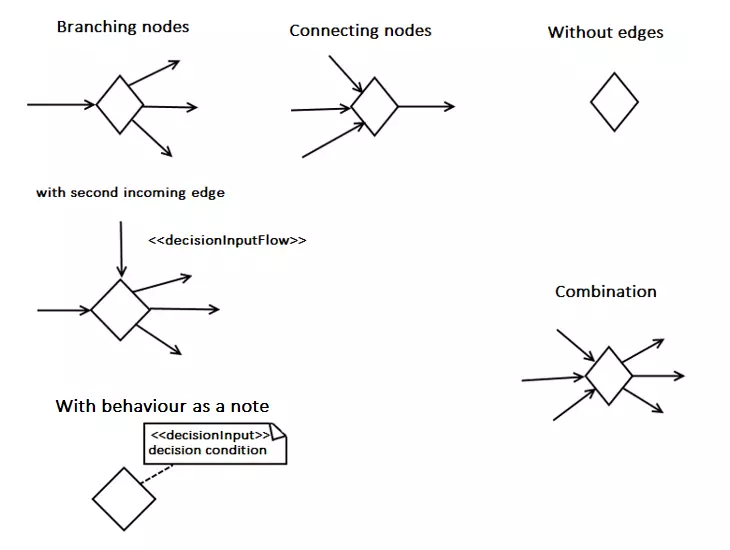
Branching nodes and connecting nodes (decision nodes and merge nodes) also share the same symbol in the activity diagram. The flow control is one of the distinguishing features of these node notations. A branching node requires at least one, or two incoming edges at the most. UML names one the “primary incoming edge” and the second is called “decision input flow.” Whether outgoing flows represent object or control flows depends on the type of primary edge. The task of the node is to choose between outgoing edges. The node offers its inbound node without copying it. So the token can only take one way.
A connection node bundles several incoming flows into a single outgoing flow. Unlike the synchronisation node, the connection node does not merge tokens into a new one or synchronise the types of incoming edges. So, for an outgoing control flow, all incoming edges must also be control flows. The same applies to object flows. The connection node simply offers all incoming tokens for the outgoing edge.
If you want to create an activity diagram in UML and edit the concept in a team, it is important to adhere to the notation. This is the only way to ensure the general comprehensibility of this graphical modeling language. In this article, we have introduced the most important activity nodes and edges with their functions. We have also presented all basic and specific notations for activity diagrams according to UML 2.5.1 specification. The exhaustively explained specification of all UMP activity diagram icons can be found on the Object Management Group website.


